Rectifier circuit diagram Fyp1-2 progress evaluations Full wave bridge rectifier supply
Draw the circuit diagram of a full wave rectifier Briefly explain its
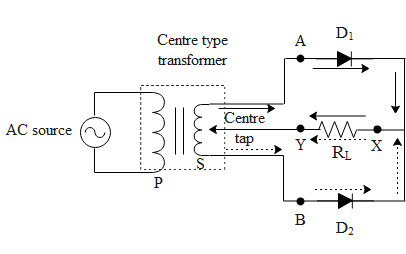
Draw the circuit diagram of a full wave rectifier briefly explain its Solved figure below shows the circuit diagram of a full-wave Wave full diagram rectifier electronicscoach circuit center tap working source
Full wave bridge rectifier
Rectifier bridge wave full supply micro diagram digital detailFull rectifier circuit diagram Full wave bridge rectifier schematicFull wave circuit diagram.
Rectifier transformer tapped output waveform inputCircuitlab wave full circuit description What is single phase full wave controlled rectifier? working, circuitFull wave bridge rectifier circuit diagram.
900w full-wave circuit diagram
How the half wave rectifier circuit works wiring view and schematicsDraw the circuit diagram of a half wave rectifier and explain its working. Full wave controlled rectifier circuit diagram10+ full wave diagram.
What is full wave rectifier circuit diagram working advantagesWhat is single phase full wave controlled rectifier with rl load Rectifier circuit diagramRectifier waveform.

Rectifier capacitor resistor transcription electrical
Full waveIn-depth guide to full wave rectifier Full wave rectifier schematicFull wave rectification diagram.
[solved] only problem 2! repeat problem 1 for the full-wave bridgeFull wave rectifier and bridge rectifier theory Rectifier wave circuit full tapped center filter bridge without diodes diagram tap using types rectifiers power supply circuitdigest ac fourIn-depth guide to full wave rectifier.

Full wave bridge rectifier circuit diagram
Circuit diagram 900w wave full seekicThe full-wave bridge rectifier Full wave rectifier circuit diagram (center tapped & bridge rectifier).
.


The Full-Wave Bridge Rectifier - Last Minute Engineers
![[Solved] Only problem 2! Repeat Problem 1 for the full-wave bridge](https://i2.wp.com/www.coursehero.com/qa/attachment/3974530/)
[Solved] Only problem 2! Repeat Problem 1 for the full-wave bridge

Full Wave Bridge Rectifier Circuit Diagram - Riset

Full Wave Rectifier Circuit Diagram (Center Tapped & Bridge Rectifier)

How The Half Wave Rectifier Circuit Works Wiring View And Schematics

In-Depth Guide to Full Wave Rectifier - Circuit Diagram, Waveform

Full Wave Controlled Rectifier Circuit Diagram

Solved Figure below shows the circuit diagram of a full-wave | Chegg.com
